Arduino and the I2C bus
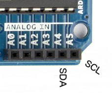
From a hardware perspective, the wiring is very easy. Those of you with an Arduino Uno or 100% compatible board, you will be using pins A4 for SDA (data) and A5 for SCL (clock):
If you are using an Arduino Mega, SDA is pin 20 and SCL is 21, so note that shields with I2C
need to be specifically for the Mega. If you have another type of board, check your data sheet
or try the Arduino team’s hardware website. And finally, if you are using a bare DIP
ATmega328-PU microcontroller, you will use pins 27 for SDA and 28 for SCL. The bus wiring is
simple: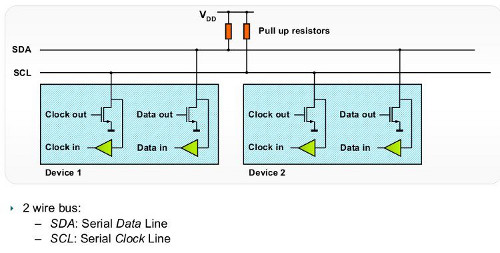
If you are only using one I2C device, the pull-up resistors are (normally) not required, as the ATmega328 microcontroller in our Arduino has them built-in. However if you are running a string of devices, use two 10 kilo ohm resistors. Like anything, some testing on a breadboard or prototype circuit will determine their necessity. Sometimes you may see in a particular device’s data sheet the use of different value pull-up resistors – for example 4.7k ohm. If so, heed that advice. The maximum length of an I2C bus is around one metre, and is a function of the capacitance of the bus. This distance can be extended with the use of a special IC, which we will examine during the next I2C chapter.
Each device can be connected to the bus in any order, and devices can be masters or slaves. In our Arduino situation, the board is the master and the devices on the I2C bus are the slaves. We can write data to a device, or read data from a device. By now you should be thinking “how do we differentiate each device on the bus?”… Each device has a unique address. We use that address in the functions described later on to direct our read or write requests to the correct device. It is possible to use two devices with identical addresses on an I2C bus, but that will be discussed in a later article.
As like most devices, we make use of an Arduino library, in this case <wire.h>. Then use the function Wire.begin(); inside of void setup() and we’re ready to go.
Sending data from our Arduino to the I2C devices requires two things: the unique device address (we need this in hexadecimal) and at least one byte of data to send. For example, the address of the part in example 20.1 (below) is 00101111 (binary) which is 0X2F in hexadecimal. Then we want to set the wiper value, which is a value between 0 and 127, or 0x00 and 0x7F in hexadecimal. So to set the wiper to zero, we would use the following three functions:
Wire.beginTransmission(0x2F); // part address is 0x2F or 0101111This sends the device address down the SDA (data) line of the bus. It travels along the bus, and “notifies” the matching device that it has some data coming…
Wire.write(0); // sends 0 down the busThis sends the byte of data to the device – into the device register (or memory of sorts), which is waiting for it with open arms. Any other devices on the bus will ignore this. Note that you can only perform one I2C operation at a time! Then when we have finished sending data to the device, we “end transmission”. This tells the device that we’re finished, and frees up the I2C bus for the next operation:
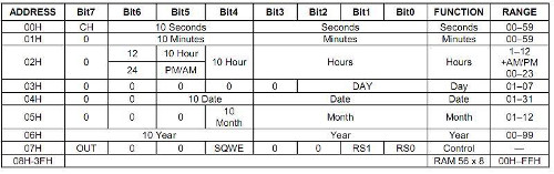
Wire.endTransmission();Some devices may have more than one register, and require more bytes of data in each transmission. For example, the DS1307 real-time clock IC has eight registers to store timing data, each requiring eight bits of data (one byte):
However with the DS1307 – the entire lot need to be rewritten every time. So in this case we would use eight wire.send(); functions every time. Each device will interpret the byte of data sent to it, so you need the data sheet for your device to understand how to use it.
Receiving data from an I2C device into our Arduino requires two things: the unique device address (we need this in hexadecimal) and the number of bytes of data to accept from the device. Receiving data at this point is a two stage process. If you review the table above from the DS1307 data sheet, note that there is eight registers, or bytes of data in there. The first thing we need to do is have the I2C device start reading from the first register, which is done by sending a zero to the device:
Wire.beginTransmission(device_address);
Wire.write(0);
Wire.endTransmission();Wire.requestFrom(device_address, 3);Which tells the device to send three bytes of data back to the Arduino. We then immediately follow this with:
*a = Wire.read();
*b = Wire.read();
*c = Wire.read();
We do not need to use Wire.endTransmission() when reading data. Now that the requested data is in their respective variables, you can treat them like any ordinary byte variable. For a more detailed explanation of the I2C bus, read this explanatory document by NXP. Now let’s use our I2C knowledge by controlling a range of devices…
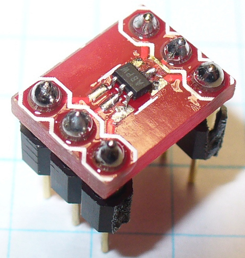
The Microchip MCP4018T digital linear potentiometer. The value of this model is 10 kilo ohms. Inside this tiny, tiny SMD part is a resistor array consisting of 127 elements and a wiper that we control by sending a value of between 0 and 127 (in hexadecimal) down the I2C bus. This is a volatile digital potentiometer, it forgets the wiper position when the power is removed. However naturally there is a compromise with using such a small part, it is only rated for 2.5 milliamps – but used in conjunction with op amps and so on. For more information, please consult the data sheet. As this is an SMD part, for breadboard prototyping purposes it needed to be mounted on a breakout board. Here it is in raw form:
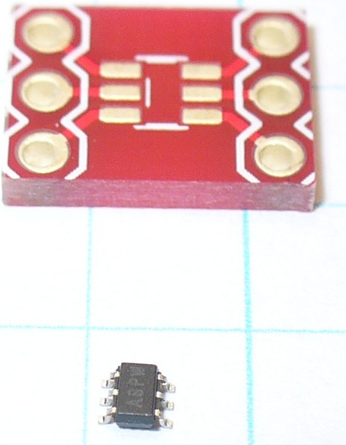
Above the IC is a breakout board. Consider that the graph paper is 5mm square! It is the incorrect size, but all I have. However soldering was bearable. Put a drop of solder on one pad of the breakout board, then hold the IC with tweezers in one hand, and reheat the solder with the other hand – then push the IC into place. A few more tiny blobs of solder over the remaining pins, and remove the excess with solder wick. Well … it worked for me:
Our example schematic is as follows:
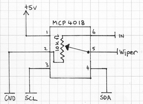
As you can see, the part is simple to use, your signal enters pin 6 and the result of the voltage division is found on pin 5. Please note that this is not a replacement for a typical mechanical potentiometer, we can’t just hook this up as a volume or motor-speed control! Again, please read the data sheet.
Control is very simple, we only need to send one byte of data down, the hexadecimal reference point for the wiper, e.g.:
Wire.beginTransmission(0x2F);      // part address is 0x2F or 0101111b
Wire.write(0x3F); //
Wire.endTransmission();
Here is a quick demonstration that moves the wiper across all points:
// Example 20.1

int dt = 2000; // used for delay duration
byte rval = 0x00; // used for value sent to potentiometer
#include "Wire.h"
#define pot_address 0x2F // each I2C object has a unique bus address, the MCP4018 is 0x2F or 0101111 in binary

void setup()
{
  Wire.begin();
  Serial.begin(9600);
}

void potLoop()
// sends values of 0x00 to 0x7F to pot in order to change the resistance
// equates to 0~127
{
  for (rval=0; rval<128; rval++)
  {
    Wire.beginTransmission(pot_address);
    Wire.write(rval); //
    Wire.endTransmission();
    Serial.print(" sent - ");
    Serial.println(rval, HEX);
    delay(dt);
  }
}

void loop()
{
  potLoop();
}
and a video demonstration:https://www.youtube.com/watch?v=ii5hy-pXsLU&feature=youtu.be
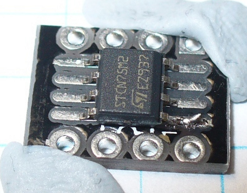
Now we will read some data from an I2C device. Our test subject is the ST Microelectronics CN75 temperature sensor. Again, we have another SMD component, but the CN75 is the next stage larger than the part from example 20.1. Thankfully this makes the soldering process much easier, however still requiring some delicate handiwork:
The rest is on website: http://tronixstuff.com/2010/10/20/tutorial-arduino-and-the-i2c-bus/
Some interesting examples:
Wire.beginTransmission(0x68);
Wire.write(0);
Wire.endTransmission();
Wire.requestFrom(DS1307_I2C_ADDRESS, 7);
*second     = bcdToDec(Wire.read();
*minute     = bcdToDec(Wire.read();
*hour       = bcdToDec(Wire.read();
*dayOfWeek  = bcdToDec(Wire.read());
*dayOfMonth = bcdToDec(Wire.read());
*month      = bcdToDec(Wire.read());
*year       = bcdToDec(Wire.read());
Wire.write(0);
Wire.write(decToBcd(second));
Wire.write(decToBcd(minute));
Wire.write(decToBcd(hour));
Wire.write(decToBcd(dayOfWeek));
Wire.write(decToBcd(dayOfMonth));
Wire.write(decToBcd(month));
Wire.write(decToBcd(year));
Wire.endTransmission();/*
DS1307 Square-wave machine
Used to demonstrate the four different square-wave outputs from Maxim DS1307
See page nine of data sheet for more information
John Boxall - tronixstuff.com
*/
#include "Wire.h"
#define DS1307_I2C_ADDRESS 0x68 // each I2C object has a unique bus address, the DS1307 is 0x68
void setup()
{
Wire.begin();
}
void sqw1() // set to 1Hz
{
Wire.beginTransmission(DS1307_I2C_ADDRESS);
Wire.write(0x07); // move pointer to SQW address
Wire.write(0x10); // sends 0x10 (hex) 00010000 (binary)
Wire.endTransmission();
}
void sqw2() // set to 4.096 kHz
{
Wire.beginTransmission(DS1307_I2C_ADDRESS);
Wire.write(0x07); // move pointer to SQW address
Wire.write(0x11); // sends 0x11 (hex) 00010001 (binary)
Wire.endTransmission();
}
void sqw3() // set to 8.192 kHz
{
Wire.beginTransmission(DS1307_I2C_ADDRESS);
Wire.write(0x07); // move pointer to SQW address
Wire.write(0x12); // sends 0x12 (hex) 00010010 (binary)
Wire.endTransmission();
}
void sqw4() // set to 32.768 kHz (the crystal frequency)
{
Wire.beginTransmission(DS1307_I2C_ADDRESS);
Wire.write(0x07); // move pointer to SQW address
Wire.write(0x13); // sends 0x13 (hex) 00010011 (binary)
Wire.endTransmission();
}
void sqwOff()
// turns the SQW off
{
Wire.beginTransmission(DS1307_I2C_ADDRESS);
Wire.write(0x07); // move pointer to SQW address
Wire.write(0x00); // turns the SQW pin off
Wire.endTransmission();
}
void loop()
{
sqw1();
delay(5000);
sqw2();
delay(5000);
sqw3();
delay(5000);
sqw4();
delay(5000);
sqwOff();
delay(5000);
}